Signal Anatomy Slides Unit: Signal Masters | Lesson 1 of 3
Standard 7.MS-ETS3-1
Systems Engineering Fundamentals
Signal Anatomy
How do messages travel from a human mind across air, wires, and space to be understood?
The Mission
Deconstruct 6 universal components
The Method
Reverse-engineer modern communication
The Outcome
Map any signal network on Earth
The Mystery of Transmission
Concept 01
Thoughts cannot fly through the air on their own.
Imagine you want to send the word "HELLO" to someone 5 miles away. Your brain creates the message, but vocal cords cannot shout that far.
Essential Question: What physical steps and devices are required to transform a thought into an electrical or light wave, send it, and rebuild it into thought?
1
Information must be generated
2
It must convert into a transmittable code
3
Energy carries the code through a medium
4
Receiver captures and translates it back
Every system from ancient smoke signals to smartphones uses the exact same 6 components.
The 6 Fundamental Components
Standard 7.MS-ETS3-1
1
Source
The origin of the information or message (e.g., human brain, camera sensor, weather station).
2
Encoder
Converts the message into a signal or code (e.g., microphone, keyboard, Morse code tapper).
3
Transmitter
Sends the coded signal across a channel or medium (e.g., radio antenna, fiber-optic LED, wire).
4
Receiver
Captures the transmitted signal from the environment (e.g., dish antenna, photo-sensor, ear).
5
Decoder
Reconverts the signal into human-readable or usable form (e.g., speaker, screen, codebook).
6
Storage
Preserves data for later retrieval or buffer processing (e.g., flash memory, server hard drive, paper log).
Source → Encoder → Transmitter ⎯⎯ [Channel] ⎯⎯▶ Receiver → Decoder and Storage
Case Study: Sending a Text Message
Analysis in Action
Source
Your brain conceives: "Practice starts at 4 PM"
Encoder
Touchscreen converts keystrokes into binary data (0s and 1s)
Transmitter
Internal phone antenna pulses radio frequency waves to cell tower
Receiver
Friend's phone antenna detects and captures the radio wave pulses
Decoder
Microprocessor converts 0s and 1s into glowing pixels spelling text
Storage
Cell carrier database and phone flash memory save the message history
What happens if even ONE component fails? The communication chain completely breaks.
Hands-On Investigation
Lab Protocol
Your Team Task
Open the Component Breakdown Worksheet.
Deconstruct a mystery non-digital system (Tin-Can Phone, Morse Telegraph, or Light Blink).
Isolate and label all 6 components with physical evidence.
Simulate a component failure and record the exact breakdown point.
Systems Rule #1
A component is defined by its function, not its appearance.
Systems Rule #2
Storage does not have to be electronic—it can be written ink, punch cards, or magnetic tape!
Ready? Form pairs and review your lab station tools. Time: 25 Minutes
Component Breakdown Worksheet Systems Engineering Investigation • 7.MS-ETS3-1
Component Breakdown Worksheet
Lesson 1: Anatomy of Signals
Student Name:
Date:
Period/Team:
1
The 6 Fundamental Components
Match each component term to its systems function by writing the correct letter in the blank.
[ _ ] 1. Source
[ _ ] 2. Encoder
[ _ ] 3. Transmitter
[ _ ] 4. Receiver
[ _ ] 5. Decoder
[ _ ] 6. Storage
A. Retains data for later retrieval or processing.
B. Converts received signal into human-usable form.
C. Converts information into a code or signal pulse.
D. Captures incoming energy pulses from medium.
E. Originator of the thought, message, or reading.
F. Sends coded signal through a transmission path.
2
Case Study: Walkie-Talkie Radio Transmission
Two rangers communicate across a canyon: Ranger Maya says "Trail 4 is clear." Fill in the component breakdown.
Component Specific Device / Part in this System Physical Energy or Signal Form Source
|
| Encoder |
|
|
| Transmitter |
|
|
| Receiver |
|
|
| Decoder |
|
|
| Storage |
|
|
Systems Engineering Check:
If Ranger Maya speaks when the receiver radio is turned off, the audio is permanently lost. Which component must be incorporated so the ranger can hear the message later? Explain how it functions.
Signal Masters • Lesson 1 Page 1 of 2
Hands-On Reverse Engineering
Physical System Deconstruction
Lab Station Analysis
3
Your Lab Station Device
Inspect your assigned physical communication setup (e.g., Optical Light Signaling, Acoustic String Intercom, or Wired Buzzer).
Device Tested:
Transmission Medium:
System Architecture Diagram
Draw the step-by-step path of communication. Label each component: Source, Encoder, Transmitter, Receiver, Decoder, Storage .
4
Component Evidence Log
Signal Anatomy Teacher Guide Teacher Implementation Guide
Signal Anatomy Teacher Guide
Standard: 7.MS-ETS3-1
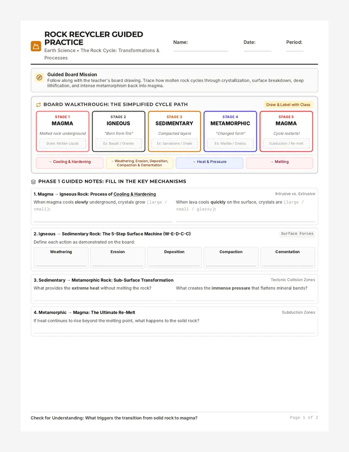
Warm-Up (7m) The 5-Mile Shout
Direct (12m) 6 Component Intro
Lab Stations (20m) Reverse Engineering
Debrief (6m) Failure Mode Check
Low-Cost Lab Station Setups (Prepare 3 Options)
Station A: Optical Light
Flashlight + index card with pinhole/color filter + printed Morse key sheet. Medium: Visible light photons.
Station B: Acoustic Cup
2 paper cups + 15ft taut string + paperclip anchoring diaphragm. Medium: Mechanical kinetic waves in string.
Station C: Simple Telegraph
9V battery + paperclip contact switch + mini buzzer/LED on cardboard. Medium: Direct electric current in wires.
Common 7th-Grade Misconceptions
• Encoder vs. Transmitter: Students often combine these. Reinforce: Encoder makes code; Transmitter emits energy into the medium.
• Forgetting Storage: Students think storage is only "cloud hard drives." Emphasize paper logs, voice recorders, buffers, or RAM caches.
• Voice as Radio: Believing sound itself travels through cell antennas rather than electromagnetic waves.
Strategic Facilitation Prompts
• "Point to the exact surface where energy converts from acoustic pressure into electrical signals."
• "If I cut the string or block the beam, which component failed: the transmitter or the channel?"
• "Why does human language itself qualify as an encoded system of arbitrary symbols?"
Worksheet Master Answer Key
Part 1 Matching:
1: E (Source) | 2: C (Encoder) | 3: F (Transmitter) | 4: D (Receiver) | 5: B (Decoder) | 6: A (Storage)
Critical Thinking Prompt:
Incorporate an audio storage module (e.g., solid-state flash memory / voicemail buffer). When receiver powers on, stored memory plays back.
Part 2 Walkie-Talkie Case Study:
• Source: Ranger Maya's vocal cords / brain (acoustic pressure).
• Encoder: Radio microphone capsule (converts sound into electric audio signal).
• Transmitter: Radio circuit & antenna (emits modulated RF waves).
• Receiver: Receiving antenna & tuner (detects RF electromagnetic waves).
• Decoder: Audio amplifier & speaker diaphragm (converts RF signal back into sound waves).
• Storage: Radio EEPROM / base station transmission recorder.
Signal Masters • Lesson 1 Teacher Guide Standards: 7.MS-ETS3-1
System Feedback Slides Unit: Signal Masters | Lesson 2 of 3
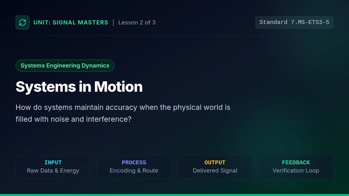
Standard 7.MS-ETS3-5
Systems Engineering Dynamics
Systems in Motion
How do systems maintain accuracy when the physical world is filled with noise and interference?
INPUT
Raw Data & Energy
PROCESS
Encoding & Route
OUTPUT
Delivered Signal
FEEDBACK
Verification Loop
The Universal Systems Model
Concept 01
1. INPUT
Data, electrical power, keystrokes, or physical stimuli entering the system boundary.
2. PROCESS
Operations performed on the input: encoding, modulation, amplification, and transmission.
3. OUTPUT
The result produced: synthesized audio, displayed text, activated robotic servo, or alarm.
4. THE FEEDBACK LOOP
Information about the output is cycled back to the source to adjust or retransmit.
Closed-Loop Control
Systems engineers design feedback loops so systems monitor themselves. Self-Correcting Networks
Open-Loop vs. Closed-Loop
Core Distinction
Open-Loop System
No Feedback
The transmitter fires information into the medium and assumes it was received.
Example: Megaphone announcement
If the listener is wearing earmuffs, the speaker has zero idea the message failed!
Risk: Undetected errors & lost data.
Closed-Loop System
Active Feedback
The receiver returns an acknowledgment (ACK) or error report back to the sender.
Example: Text message "Delivered / Read"
If signal drops, the phone resends until confirmed!
Benefit: High reliability & automatic recovery.
Trade-Off: Feedback loops increase reliability, but require extra energy, bandwidth, and time.
Noise: The Enemy of Signals
Environmental Factors
Physical Interference
Walls blocking radio waves, fog obscuring laser light, or friction dampening string vibrations.
Electromagnetic Noise
Power lines, solar flares, or competing radio stations corrupting the waveform frequency.
Engineering Defenses
Engineers use parity checks, repeaters, shielded cables, and confirmation handshakes.
Key Principle: You cannot eliminate all environmental noise. You must engineer systems that detect corrupted outputs and request retransmission!
Loop Lab Worksheet Systems Engineering Lab • 7.MS-ETS3-5
Loop Lab: Open vs. Closed Transmission
Lesson 2: Feedback Loops
Lead Engineer:
Partner:
Date/Period:
1
Systems Engineering Model
Complete the systems diagram below by defining the four core elements in your own words.
INPUT
Define role in system:
PROCESS
Define role in system:
OUTPUT
Define role in system:
FEEDBACK LOOP (Output → Input Adjustment): Self-Correcting Mechanism
2
Experimental Protocol: The Corrupted Signal Test
Station A (Transmitter) must send 10 numerical codes across the room through simulated ambient classroom noise (chatter, tapping, visual movement).
Condition A: Open-Loop (No Feedback)
• Sender transmits symbol once.
• Receiver records whatever is perceived.
• Rule: Receiver cannot ask questions, nod, or signal confusion.
Condition B: Closed-Loop (With Feedback)
• Sender transmits symbol.
• Receiver sends quick ACK (thumbs-up) or NAK (thumbs-down / repeat request).
• Sender retransmits if NAK received.
Engineering Hypothesis:
Predict how adding a feedback loop will affect (1) message accuracy percentage and (2) total transmission duration.
Signal Masters • Lesson 2 Page 1 of 2
Empirical Data & Systems Analysis
Transmission Results & Trade-Offs
Data Collection
3
Trial Data: 10 Symbol Transmission
Trial # Sent Code Cond. A Received A Match? Cond. B Received B Match? 1
|
|
|
|
| 2 |
|
|
|
|
|
| 3 |
|
|
|
|
|
| 4 |
|
|
|
|
|
| 5 |
|
|
|
|
Design Brief Slides Unit: Signal Masters | Lesson 3: Culminating Challenge
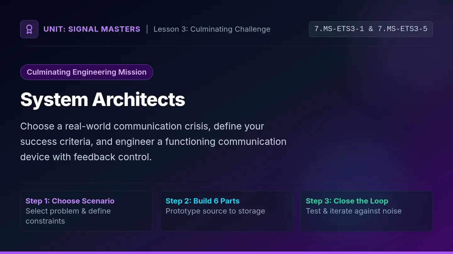
7.MS-ETS3-1 & 7.MS-ETS3-5
Culminating Engineering Mission
System Architects
Choose a real-world communication crisis, define your success criteria, and engineer a functioning communication device with feedback control.
Step 1: Choose Scenario
Select problem & define constraints
Step 2: Build 6 Parts
Prototype source to storage
Step 3: Close the Loop
Test & iterate against noise
Select Your Team's Mission Scenario
Student Choice
Mission Alpha Subterranean Cave
Trapped speleologists need to transmit vital signs through solid rock with zero line-of-sight and no cellular signals.
Key Medium: Acoustic vibration or mechanical tension.
Mission Bravo Silent Surgical Suite
Surgeons in a sterile room must send emergency supply requests to pharmacy without audible sound disturbing patient heart monitors.
Key Medium: Optical pulses or tactile feedback.
Mission Charlie Mars Dust Storm Rover
A remote planetary rover must buffer atmospheric readings during heavy dust storms until orbital satellite pass-over.
Key Medium: Storage caching and delayed retransmission.
Mission Delta Wildfire Lookout Mesh
Remote forest lookouts need to send coordinates through heavy smoke plumes when mountain power grids go completely dark.
Key Medium: Low-power reflective optical or wire relays.
Your team picks ONE scenario, analyzes the operating conditions, and engineers the solution!
System Requirements & Non-Negotiables
Standard 7.MS-ETS3-1
1. All 6 Components
Your physical build must clearly demonstrate physical parts for:
• Source • Receiver • Encoder • Decoder • Transmitter • Storage
2. Closed-Loop Feedback
Your system cannot be open-loop! It must feature:
• An acknowledgment (ACK) return path.
• A clear protocol for detecting corrupted output.
• A retransmission rule when an error occurs.
Systems Rule: A judge must be able to point to each physical part and watch data travel across the full loop!
Standard Alignment: 7.MS-ETS3-1 (Components) & 7.MS-ETS3-5 (Feedback Modeling) 100% Student-Engineered
Defining Success Criteria & Constraints
Engineering Practice
Criteria (What it must do)
How will you know your system succeeded? Your team must establish measurable targets:
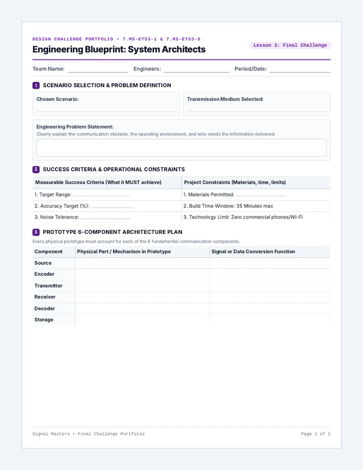
Engineering Blueprint Packet Design Challenge Portfolio • 7.MS-ETS3-1 & 7.MS-ETS3-5
Engineering Blueprint: System Architects
Lesson 3: Final Challenge
Team Name:
Engineers:
Period/Date:
1
Scenario Selection & Problem Definition
Chosen Scenario:
Transmission Medium Selected:
Engineering Problem Statement:
Clearly explain the communication obstacle, the operating environment, and who needs the information delivered.
2
Success Criteria & Operational Constraints
Measurable Success Criteria (What it MUST achieve) Project Constraints (Materials, time, limits) 1. Target Range: 1. Materials Permitted: 2. Accuracy Target (%): 2. Build Time Window: 35 Minutes max 3. Noise Tolerance: 3. Technology Limit: Zero commercial phones/Wi-Fi
3
Prototype 6-Component Architecture Plan
Every physical prototype must account for each of the 6 fundamental communication components.
Component Physical Part / Mechanism in Prototype Signal or Data Conversion Function Source
|
| Encoder |
|
|
| Transmitter |
|
|
| Receiver |
|
|
| Decoder |
|
|
| Storage |
|
|
Signal Masters • Final Challenge Portfolio Page 1 of 2
Prototyping & Iteration Log
System Schematic & Testing Verification
Build & Validation
4
Prototype Systems Schematic
Draw your system blueprint. Diagram: (1) Input, (2) Process stages, (3) Output, (4) Transmission medium, and (5) The Feedback Return Loop.
5
Closed-Loop Feedback Protocol
1. Acknowledgment (ACK) Signal:
How does the receiver confirm a successful message?
2. Error / Resend (NAK) Protocol:
How does the receiver demand a retransmission?
6
Iterative Testing Log: Baseline vs. Redesign
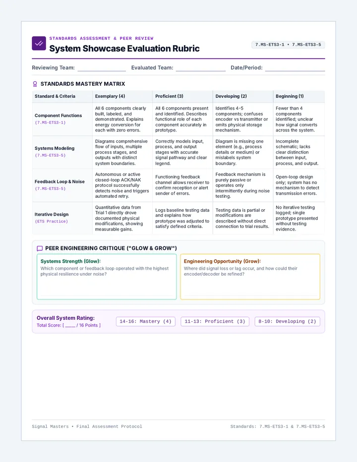
System Showcase Rubric Standards Assessment & Peer Review
System Showcase Evaluation Rubric
7.MS-ETS3-1 • 7.MS-ETS3-5
Reviewing Team:
Evaluated Team:
Date/Period:
Standards Mastery Matrix
Standard & Criteria Exemplary (4) Proficient (3) Developing (2) Beginning (1) Component Functions (7.MS-ETS3-1) All 6 components clearly built, labeled, and demonstrated. Explains energy conversion for each with zero errors. All 6 components present and identified. Describes functional role of each component accurately in prototype. Identifies 4-5 components; confuses encoder vs transmitter or omits physical storage mechanism. Fewer than 4 components identified; unclear how signal converts across the system. Systems Modeling (7.MS-ETS3-5) Diagrams comprehensive flow of inputs, multiple process stages, and outputs with distinct system boundaries. Correctly models input, process, and output stages with accurate signal pathway and clear legend. Diagram is missing one element (e.g., process details or medium) or mislabels system boundary. Incomplete schematic; lacks clear distinction between input, process, and output. Feedback Loop & Noise (7.MS-ETS3-5) Autonomous or active closed-loop ACK/NAK protocol successfully detects noise and triggers automated retry. Functioning feedback channel allows receiver to confirm reception or alert sender of errors. Feedback mechanism is purely passive or operates only intermittently during noise testing. Open-loop design only; system has no mechanism to detect transmission errors. Iterative Design (ETS Practice) Quantitative data from Trial 1 directly drove documented physical modifications, showing measurable gains. Logs baseline testing data and explains how prototype was adjusted to satisfy defined criteria. Testing data is partial or modifications are described without direct connection to trial results. No iterative testing logged; single prototype presented without testing evidence.
Peer Engineering Critique ("Glow & Grow")
Systems Strength (Glow):