Subsystem Blueprint Slides Payload Pioneers • Unit 1
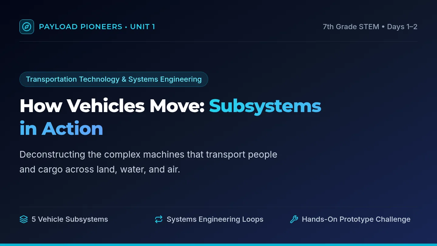
7th Grade STEM • Days 1–2
Transportation Technology & Systems Engineering
How Vehicles Move: Subsystems in Action
Deconstructing the complex machines that transport people and cargo across land, water, and air.
5 Vehicle Subsystems
Systems Engineering Loops
Hands-On Prototype Challenge
Systems Context
Transportation Infrastructure
Moving People and Cargo
A transportation vehicle never operates in isolation—it relies on an interconnected transit network.
Terminals
Stations, airports, and shipping ports where passengers board and cargo is safely loaded or unloaded.
Hubs of Transit
Travel Lanes
Designated pathways such as highways, shipping channels, rail lines, and commercial flight corridors.
Defined Corridors
Communications
Traffic lights, air traffic control radars, GPS signals, and vehicle-to-vehicle wireless monitoring.
Control & Safety
Key Design Element: Vehicle shape is optimized for passenger safety or maximum cargo volume.
Vehicle Anatomy
5 Subsystems
The Five Vehicle Subsystems
Every vehicle relies on five integrated subsystems to achieve safe and efficient motion.
1. Structural
Chassis, frame, hull, or fuselage supporting cargo, passengers, and components.
The Backbone
2. Propulsion
Engine, motor, sails, or pedals converting energy to thrust and forward motion.
The Engine
3. Guidance
GPS, compass, maps, and sensors providing navigation info along the travel route.
The Navigator
4. Suspension
Shock absorbers, springs, boat keels, or airplane wings keeping the ride stable.
The Cushion
5. Control
Steering wheels, rudders, elevators, and brakes regulating speed and heading.
The Driver
Notice the difference: Guidance tells you where to go, while Control changes speed or direction!
Cross-Domain Analysis
Car • Sailboat • Airplane
Subsystems Across Domains
Different mediums (road, water, air) require specialized engineering solutions.
Subsystem Car (Land) Sailboat (Water) Small Airplane (Air) Structural Steel / aluminum chassis Fiberglass hull & mast Fuselage & aluminum ribs Propulsion Gas engine / electric motor Mainsail & jib catching wind Propeller + combustion engine Guidance GPS display & road signs Nautical charts & compass Altimeter, radar, waypoint GPS Suspension Coil springs & rubber tires Weighted keel & hull bouyancy Wing aerofoils (lift) & struts Control Steering wheel & disc brakes Rudder tiller & sail sheets Ailerons, elevators, rudder pedal
Takeaway: Even though parts look completely different, all vehicles must solve the same 5 subsystem problems!
Engineering Method
Standard 7.ETS.3.5
Systems Engineering: The 4 Elements
A system is an organized group of parts working together to accomplish a specific goal.
STEP 1
INPUTS
Resources entering the system: fuel, electricity, wind, cargo load, driver steering commands.
What Goes In
STEP 2
PROCESSES
Actions performed: burning fuel, spinning wheels, converting wind to lift, calculating route.
How It Works
STEP 3
OUTPUTS
The end results: cargo moved 5 miles, velocity, exhaust gases, heat, acoustic vibrations.
What Comes Out
STEP 4
FEEDBACK
Output information monitored and fed back to adjust inputs: speedometer readouts, tire slip alerts.
The Adjustment Loop
System Engineering Formula: Inputs → Processes → Outputs ⇄ Feedback Adjustment Loop
Dynamic Feedback
Applied Case Study
Case Study: Cruise Control Feedback Loop
How an autonomous or human driver system maintains constant highway speed on hills.
Condition Change
Hill Encountered
Vehicle starts climbing a steep grade. Gravity opposes motion, causing the car to slow down from 60 mph to 54 mph.
Sensor Feedback
Error Detected
Wheel speed sensor detects the 6 mph drop below target speed. System calculates needed power adjustment.
System Action
Input Corrected
Throttle opens wider, delivering more fuel and air to the engine. Velocity returns safely to target 60 mph!
Your Engineering Mission Ahead: You will design your own cargo vehicle and engineer a feedback loop to improve its speed and stability!
Systems Mapping Handout Payload Pioneers • Systems Engineering Investigation
Vehicle Subsystems Matrix
Name:
Date: Period:
Transportation Subsystems: 1. Structural • 2. Propulsion • 3. Guidance • 4. Suspension • 5. Control
1 Transit Network Elements
Terminal Example:
Where cargo/passengers load or board:
Travel Lane Example:
Dedicated physical pathway:
Communication / Control:
Signal or control device:
2 Subsystem Decomposition Across Three Vehicles
Identify the specific part or mechanism that accomplishes each subsystem function for each vehicle type.
Subsystem & Role Passenger Car (Land) Cargo Sailboat (Water) Cargo Airplane (Air) Structural Supports load & frame Propulsion Creates forward thrust Guidance Provides navigation data Suspension Smooths ride & balances Control Changes speed/direction
Design Analysis: Maximizing Capacity
How does the physical shape of a cargo airplane differ from a passenger jet, and why does this structural shape maximize cargo payload?
Page 1 of 2 • Subsystems Analysis
Systems Engineering Studio • Standard 7.ETS.3.5
Modeling Transportation Systems
Inputs • Processes • Outputs • Feedback
Engineering Loop Diagram
3 Complete the Vehicle System Engineering Model
Select one vehicle (e.g., an electric city bus, a drone delivery vehicle, or a high-speed cargo train) and define its systemic components.
Chosen Vehicle System: Primary Goal:
1. System Inputs
Energy, materials, operator commands, payload mass, external forces:
2. System Processes
Actions, conversions, guidance calculations, power transmission:
3. System Outputs
Desired result (displacement) plus byproducts (heat, noise, emissions):
4. Feedback Loop & Sensor Corrections Continuous Dynamic Adjustment
What sensor or driver observation measures output performance, and what input or process is adjusted when an error occurs?
4 Troubleshooting the Subsystems
Scenario: A delivery vehicle is loaded with double its normal cargo payload. When it reaches a curve in wet weather, it skids outward.
Subsystem Facilitation Guide Teacher Facilitation & Instructional Architecture
Payload Pioneers • Unit Guide
7th Grade STEM
6 Class Periods Unit
Transportation Standard
Research & communicate how transit systems move people & goods. Identify vehicle subsystems: structural, propulsion, guidance, suspension, control. Analyze design elements (shape, terminals, travel lanes).
Standard 7.ETS.3.5
Use systems engineering to model inputs, processes, outputs, and feedback among components of a transportation system to understand and optimize system behavior.
6-Period Instructional Pacing Sequence
Day 1
Transportation Networks & Subsystem Decomposition
Launch with Subsystem Blueprint Slides. Compare car, sailboat, and small airplane. Students collaborate on Part 1 & 2 of the Systems Mapping Handout. Focus on cargo vs passenger capacity trade-offs.
Day 2
Systems Engineering: Inputs, Processes, Outputs, & Feedback
Unpack standard 7.ETS.3.5 using cruise control and autopilot examples. Students complete systems diagrams on Handout Page 2 and analyze vehicle failure scenarios. Introduce the engineering challenge context.
Day 3
Hands-on Challenge Launch: The Cargo Cruiser Prototyping
Present Cargo Challenge Slides. Teams define specs, sketch schematics in their Engineering Design Journal, inventory materials, and construct their structural chassis.
Day 4
Subsystem Integration & Alpha Field Testing
Teams install propulsion (balloon/elastic), guidance (rails/stabilizers), suspension (cushioning/bearing axles), and control (tether/braking). Conduct initial baseline test runs carrying 100g standard cargo.
Day 5
Feedback Loops & Beta Optimization Trials
Teams record multi-trial test data in Journal Page 2. Identify subsystem bottlenecks (e.g. friction in axles, chassis yaw). Apply redesign iterations based on empirical feedback. Final performance trials.
Day 6
Technical Briefing Symposium & Systems Debrief
Student teams deliver 3-minute technical briefings using the Transit Briefing Rubric. Class compares design trade-offs across groups and completes self/peer evaluation.
Critical Misconceptions to Address
Guidance vs. Control: Students conflate GPS with steering. Clarify: Guidance provides information; Control exerts physical change in direction/speed.
Suspension in Air/Water: Students think only wheeled cars have suspension. Clarify: Wings provide aerodynamic lift/damping, and boat hulls/keels dampen waves.
Output vs. Feedback: An output is the end product (speed, distance). A feedback loop returns data about that output to adjust the next input!
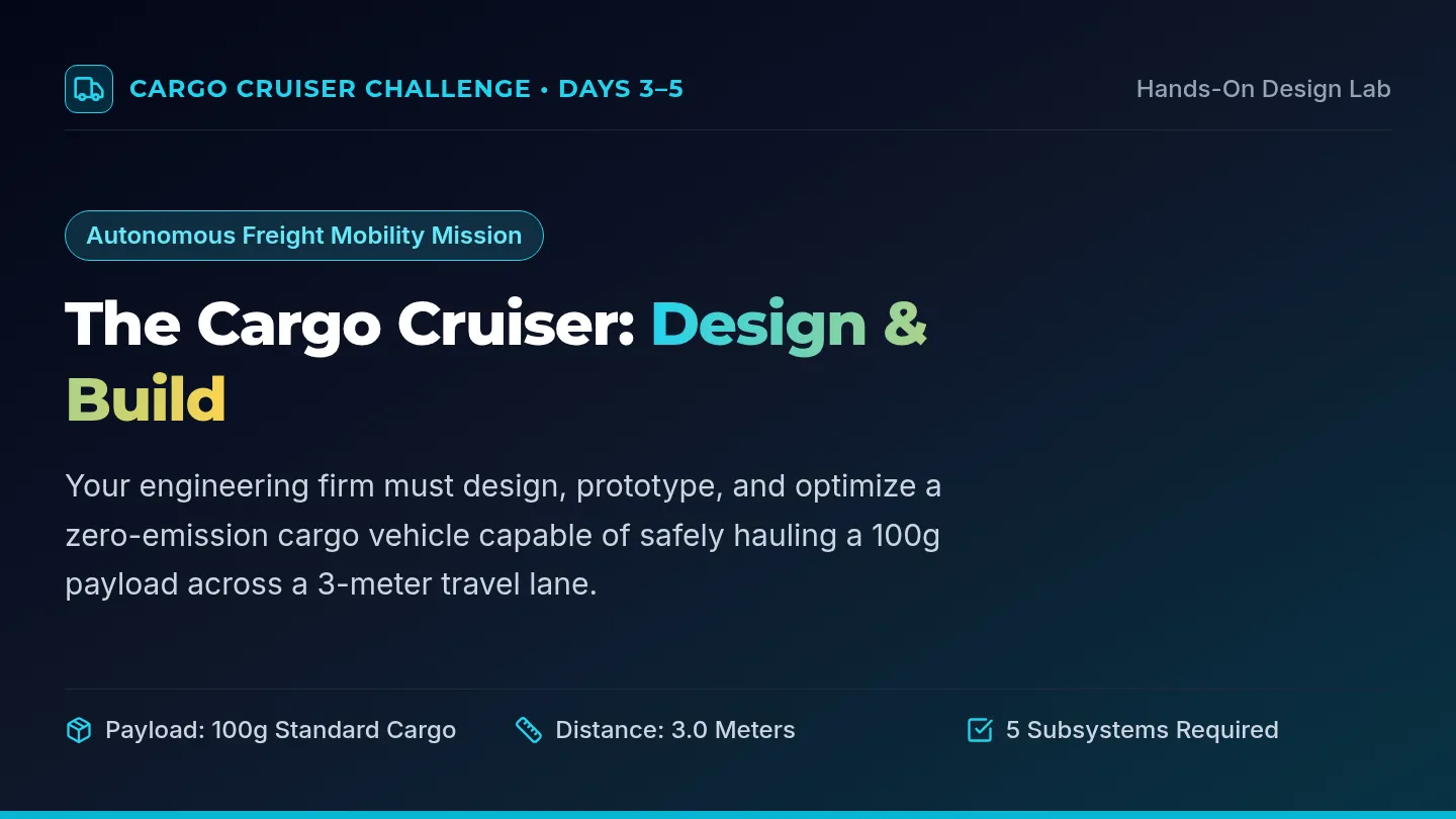
Cargo Challenge Slides Cargo Cruiser Challenge • Days 3–5
Hands-On Design Lab
Autonomous Freight Mobility Mission
The Cargo Cruiser: Design & Build
Your engineering firm must design, prototype, and optimize a zero-emission cargo vehicle capable of safely hauling a 100g payload across a 3-meter travel lane.
Payload: 100g Standard Cargo
Distance: 3.0 Meters
5 Subsystems Required
Engineering Specifications
Criteria vs Constraints
Success Criteria
• Securely transport 100 grams without cargo loss or spills.
• Complete 3.0-meter travel lane under autonomous propulsion.
• Explicitly integrate all 5 vehicle subsystems in hardware.
• Achieve steady straight-line travel within the 50cm lane.
Performance Goal: Maximum Speed & Stability
Build Constraints
• No human pushing allowed after vehicle launch release.
• Materials limited to provided workshop inventory items.
• Dimensions: Maximum 30 cm length × 20 cm width.
• Strict timeline: Prototyping (Day 3), Testing & Refinement (Days 4–5).
Challenge: Work within designated resource limits
Design Tip: Calculate your center of gravity so heavy cargo doesn't tip your vehicle!
Hardware Architecture
Prototype Subsystems
Subsystems in Your Prototype
Every team must identify how their physical model fulfills all five subsystems:
01 / STRUCT
Chassis
Cardboard base, cargo bay crate, motor mount brackets.
Carries load
02 / PROPUL
Energy Store
Rubber band elastic axle drive or inflated balloon jet thrust.
Powers motion
03 / GUID
Alignment
Parallel axle guides, tracking fins, or lane-following skids.
Keeps straight
04 / SUSP
Bearings
Straw axle sleeves, foam wheel cushions, washer bushings.
Reduces drag
05 / CTRL
Regulation
Trigger pin release, friction braking strip, nozzle restrictor.
Regulates run
You will document each subsystem in your Engineering Design Journal before testing!
Iterative Engineering
Days 4–5 Protocol
Testing & The Feedback Loop
Engineers don't guess—they test, collect data, analyze feedback, and systematically redesign.
Engineering Design Journal Cargo Cruiser Challenge • Engineering Design Process
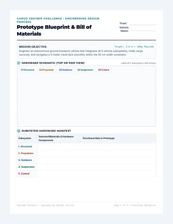
Prototype Blueprint & Bill of Materials
Team:
Vehicle Name:
Mission Objective: Target: 3.0 m • 100g Payload
Engineer an autonomous ground transport vehicle that integrates all 5 vehicle subsystems, holds cargo securely, and navigates a 3-meter travel lane smoothly within the 50 cm width constraint.
Hardware Schematic (Top or Side View)
Label all 5 subsystems with arrows
[1] Structural [2] Propulsion [3] Guidance [4] Suspension [5] Control
Subsystem Hardware Manifest
Subsystem Selected Materials & Hardware Components Functional Role in Prototype 1. Structural 2. Propulsion 3. Guidance 4. Suspension 5. Control
Payload Pioneers • Engineering Design Journal Page 1 of 2 • Prototype Blueprint
Testing & Iteration • Days 4–5
Test Trials & Feedback Optimization
Speed Formula:
\( \text{Velocity} = \frac{\Delta d}{\Delta t} \)
Performance Testing Matrix (3-Meter Track)
Record empirical data across three engineering trials. If vehicle stalls before 3 meters, record distance reached.
Trial Payload Mass (g) Distance (m) Time (s) Calculated Speed (m/s) Lane Drift (cm off line) Subsystem Performance Notes Trial 1 Alpha Baseline Trial 2 Beta Iteration 1 Trial 3 Beta Iteration 2 Final Run Official Scoring
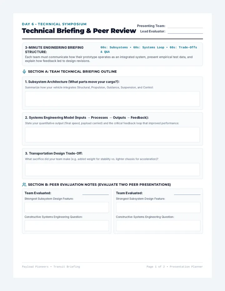
Transit Briefing Rubric Day 6 • Technical Symposium
Technical Briefing & Peer Review
Presenting Team:
Lead Evaluator:
3-Minute Engineering Briefing Structure: 60s: Subsystems • 60s: Systems Loop • 60s: Trade-Offs & Q&A
Each team must communicate how their prototype operates as an integrated system, present empirical test data, and explain how feedback led to design revisions.
Section A: Team Technical Briefing Outline
1. Subsystem Architecture (What parts move your cargo?):
Summarize how your vehicle integrates Structural, Propulsion, Guidance, Suspension, and Control:
2. Systems Engineering Model (Inputs → Processes → Outputs → Feedback):
State your quantitative output (final speed, payload carried) and the critical feedback loop that improved performance:
3. Transportation Design Trade-Off:
What sacrifice did your team make (e.g. added weight for stability vs. lighter chassis for acceleration)?
Section B: Peer Evaluation Notes (Evaluate Two Peer Presentations)
Team Evaluated:
Strongest Subsystem Design Feature:
Constructive Systems Engineering Question:
Team Evaluated:
Strongest Subsystem Design Feature:
Constructive Systems Engineering Question:
Payload Pioneers • Transit Briefing Page 1 of 2 • Presentation Planner
Standards-Based Assessment Rubric
Cargo Cruiser Evaluation Rubric
Scale: 4 • 3 • 2 • 1
Max Score: 16 Points
Criterion & Standard 4 - Exemplary 3 - Proficient 2 - Developing 1 - Beginning 1. Subsystem Integration & Function Transportation Systems Standard All 5 vehicle subsystems clearly identified and functionally integrated into physical prototype with zero omissions. Identifies and demonstrates 4–5 subsystems with minor functional redundancy or minor confusion. 3 subsystems demonstrated; conflates guidance with control or omits suspension. Fewer than 3 subsystems present; vehicle lacks coherent subsystem design. 2. Systems Engineering Modeling Standard 7.ETS.3.5 Accurately models inputs, processes, outputs, and feedback loops with clear cause-and-effect relationships and quantified data. Accurately models all 4 system components; feedback loop explained with qualitative observations. Models inputs and outputs correctly, but process description is vague or feedback loop is incomplete.