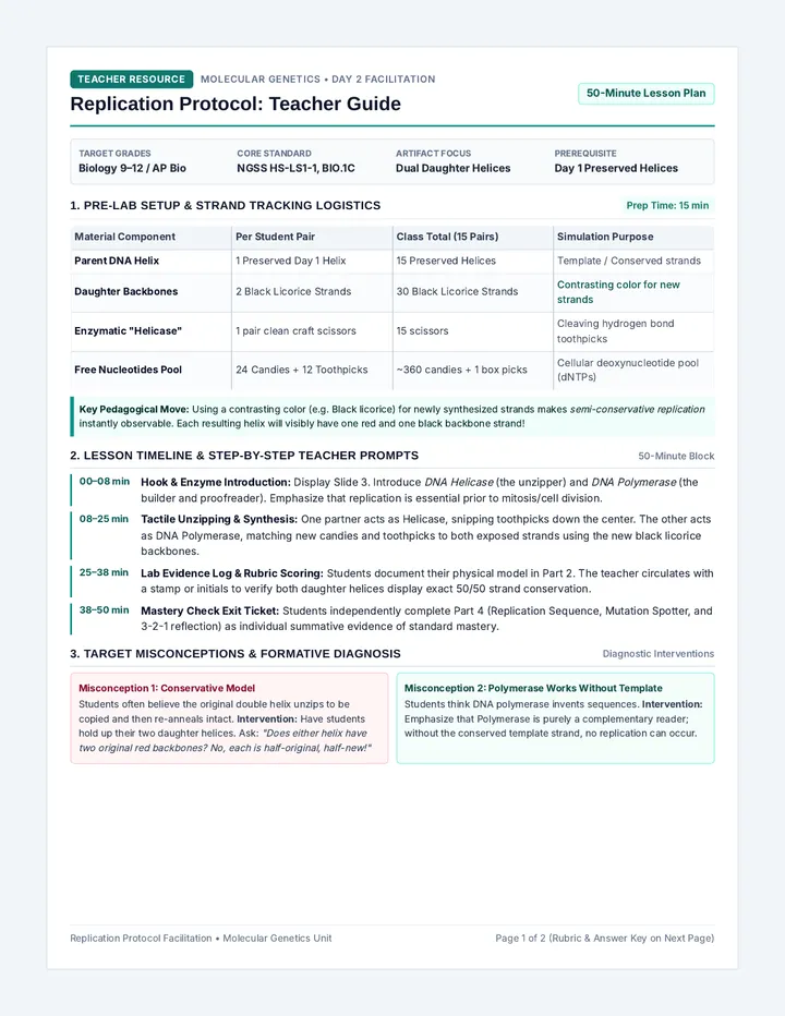
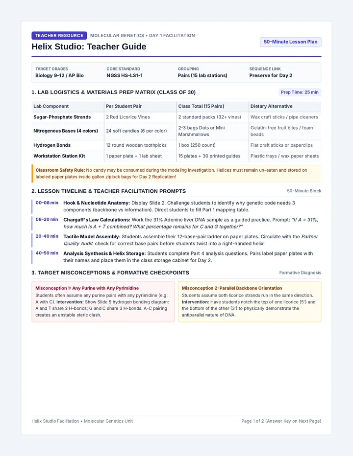
Scenario 1: High-Tension Perimeter Outrigger Cables Dominant Force: Tension
Options considered: Braided high-carbon steel cables vs. Solid cast iron struts.
Selected Material:
Material Property Justification:
Scenario 2: Ground-Level Columns Supporting 50 Stories Dominant Force: Compression
Options considered: Steel-reinforced concrete columns vs. Hollow aluminum tubes.
Selected Material:
Material Property Justification:
Scenario 3: Joint Bolts Fastening Horizontal Floor Girders to Columns Dominant Force: Shear
Options considered: High-strength steel gusset rivets vs. Standard plastic bonding anchors.
Selected Material:
Material Property Justification:
Incident Report: During a major windstorm, an unbraced 30-story commercial tower began violently swaying and corkscrew twisting. On the 12th floor, horizontal girder connection bolts sheared clean through, causing a corner vertical column to buckle outward under extreme compression.
1. What combination of lateral and vertical forces caused the joint shear and column buckling?
2. Propose one structural geometry modification (such as X-bracing) to prevent this tower failure:
Unit 1: Load Busters • Student Investigation Sheet Page 2 of 2
3. Quantitative Evaluation
Required Lab Materials & Testing Apparatus Per Class of 28 (7 Teams of 4)
Prototyping: 350 balsa/basswood sticks (1/8" sq), wood glue or low-temp glue guns, cardstock gussets.
Drafting: Grid paper (1 cm / 0.25 in), metal rulers, drafting triangles, masking tape, hobby knives.
Testing Rig: 5-gal bucket, S-hook, loading block (5x5 cm with center eyebolt), sand or barbell weights.
Measurement: Digital scales (0.1 g precision), spring scales, safety goggles (ANSI Z87.1 for all).
Load Busters Engineering Curriculum • Sequence Overview • Document 1 of 2 Page 1 of 2
Managing Student Misconceptions, Destructive Rig Controls, and Performance Rubrics
Facilitator Playbook
× Misconception 1: "More glue equals a stronger joint."
Students slather globes of glue onto connections, believing mass guarantees hold. In reality, excess glue adds severe dead weight, creates brittle failure planes, and shrinks structural efficiency.
✓ Teacher Countermeasure: "Thin Fillet & Gusset Plate"
Demonstrate that wood-to-wood contact with a micro-thin glue film and cardstock gusset plate is 300% stronger and 80% lighter than globs. Reinforce dead weight penalty during efficiency scoring.
× Misconception 2: "Square bays provide adequate framing."
Students build rectangular boxes without diagonal members, assuming vertical sticks bear all vertical load. Under minimal lateral shear or uneven loading, rectangular bays instantly parallelogram and collapse.
✓ Teacher Countermeasure: "Triangle Rigidity Test"
Have students hold a 4-pin square vs. a 3-pin triangle. Point out that triangles cannot change angles without altering side lengths, forcing shear loads into pure tension and compression paths.
× Misconception 3: "A broken tower represents a failed project."
Middle schoolers often feel demoralized when their tower snaps. They conflate structural failure with academic failure, missing the essential purpose of destructive stress-testing.
✓ Teacher Countermeasure: "The Forensic Autopsy Mindset"
Frame testing day as a forensic autopsy. Emphasize that engineers purposely push prototypes to 100% capacity to isolate the single weakest link. High grades derive from failure diagnosis and redesign insight.
Standardized Loading Protocol (Fair Test Controls)
Mandatory Lab Safety Checklist
Grading Architecture
Force Mechanics Lab (L1)20%
Blueprint & Tower Build (L2)30%
Testing Report & Autopsy (L3)30%
Redesign Defense Pitch (L3)20%
Structural Efficiency Ratio (SER) Benchmark Formula Key Evaluation Metric
\[ \text{SER} = \frac{\text{Live Load Supported (g)}}{\text{Dead Load of Tower (g)}} \]
A tower holding 12,000 g with a mass of 30 g achieves an efficiency score of 400. Scoring prioritizes high ratio over raw mass held, leveling the playing field against heavy, over-built structures.
Targeted Scaffolding (Striving Learners & ELL): Provide pre-printed 1:1 gusset templates and triangle jig guides. Use bilingual force terminology flashcards (tension/tensión, compression/compresión). Pair students strategically in 3-4 person specialist roles (Architect, Materials Manager, Quality Control Lead).
Engineering Extensions (Advanced Learners): Challenge advanced teams with dynamic lateral load testing using an oscillating box fan (simulating hurricane winds) or introduce cost-budget constraints ($100 virtual budget where sticks = $2/ea and gussets = $1/ea) to optimize cost-efficiency.
Load Busters Engineering Curriculum • Sequence Overview • Document 2 of 2 Page 2 of 2
Stations 3 & 4
Materials: Playing Card Decks • Foam Layers • Paper Fastener Pins
Procedure: Part A: Place a deck of 52 cards on a smooth table. Apply a horizontal palm force across the top card. Observe how internal friction allows parallel layers to slide past one another. Part B: Connect two cardstock strips with a single brass pin; pull opposite ways until pin cuts or card tears.
| Shear Test Setup | Applied Direction | Observed Internal Motion / Fracture |
|---|---|---|
| 1. Free Card Deck (Unpinned) | Horizontal Lateral | |
| 2. Single-Pin Cardstock Lap Joint | Opposite Pulling |
| | 3. Double-Pin + Gusset Cardstock | Opposite Pulling |
|
Shear Slip Diagram (Card Angle):
Key Analysis: How does high lateral wind against a skyscraper's facade produce shear stress on joint bolts connecting floors to columns?
Materials: Gridded Foam Beams • Rectangular Sponges • Protractors
Procedure: Secure the base end of the gridded foam beam flat against the table. Twist the top end clockwise by 45°, 90°, and 180°. Watch the square grid lines warp into diagonal diamonds. Measure the diagonal wrinkles and note where tension and compression coexist.
| Angle of Twist | Grid Distortion | Location of Greatest Surface Stress |
|---|---|---|
| 45° Rotational Twist | ||
| | 90° Rotational Twist |
|
| | 180° Severe Torque |
|
|
Torsional Distortion Sketch (45° lines):
Key Analysis: Why does torsion create diagonal tension lines (at 45°) along the exterior walls of a skyscraper during an earthquake or vortex wind?
Synthesize your observations from all four stations. In the space below, explain which structural force you anticipate will be the most dangerous threat to your team's balsa tower during vertical load testing, and identify one design feature you will include to counteract it.
Load Busters Engineering Sequence • Force Mechanics Hands-On Lab Page 2 of 2
Ground Footprint 10 cm Story Height 10 cm Per Bay • Cross-Braced Top Load Deck 8 cm
Both team engineers must verify every criterion before the skyscraper prototype can be approved for destructive stress testing.
Vertical height ≥ 40.0 cm from base to roof
Base footprint fits within 10.0 × 10.0 cm square
Rooftop level allows flat 8×8 cm load plate seating
Dry Dead Load mass ≤ 60.0 grams
Joints cured 24 hrs (no wet or tacky glue)
All 4 exterior faces cross-braced against torsion
Lead Quality Inspector Approval Skyscraper qualifies for standardized fair testing
Inspector Signature:
Tare Dead Weight: g
Unit 1: Load Busters • Tower Prototype Blueprint Page 2 of 2
Install diagonal cross-braces across all four exterior walls and at horizontal floor levels:
Every successful skyscraper tower uses X-bracing on all four sides to lock vertical geometry!
Sprint Timeline
00-05m
Finalize 40 cm tower face layout on 1:1 drafting grid. Verify all triangles are closed.
Step 1
05-25m
Pin sticks over wax paper on blueprint. Build 2 identical flat tower faces with thin glue films.
Step 2
25-42m
Join the 2 faces with cross-struts and X-braces to form 4-sided tower. Seat 8×8 cm roof plate.
Step 3
42-50m
Weigh dead load on digital scale (≤ 60.0 g). Check ≥ 40 cm height. Place on curing rack for 24h.
Step 4
Safety Protocol: Wipe excess glue immediately • Safety glasses on when cutting sticks
[ Sketch fractured 40 cm tower frame & circle initial break point ]
Based on the exact failure point identified above, propose an engineering redesign that will increase live load capacity without exceeding the 60.0 g dead load limit.
1. Structural Modification (Story Height, Cross-Bracing, or Column Splicing):
2. Material Selection Justification (Why does your proposed material/composite solve the specific force that caused failure?):
3. Dead Load Impact: How will your redesign avoid adding unnecessary dead weight?
Lead Structural Engineer Certification I verify that testing was conducted under strict fair test conditions.
Lead Engineer Signature:
Unit 1: Load Busters • Tower Destructive Lab Report Page 2 of 2
Structural efficiency measures how many times its own weight a skyscraper carries before failure.
Team Alpha: Heavy Tower
Dead Load: 58 g • Live Load: 2,320 g
Efficiency = 2,320 ÷ 58 = 40.0
Team Beta: Optimized Skyscraper
Dead Load: 34 g • Live Load: 2,720 g
Efficiency = 2,720 ÷ 34 = 80.0 (2× Winner!)
A lighter tower that carries the same load has double the structural efficiency.
NGSS Redesign Step
Step 1
Name the exact mechanical force (tension, compression, shear, torsion) that exceeded material tolerance.
"Corner column buckled"
Step 2
Propose a structural geometric change (shorter story bays, extra cross-strut, corner gusset plate).
"Add mid-story X-brace"
Step 3
Justify material selection based on specific properties (lap splice wood columns vs card gussets for shear).
"Reinforce with card gusset"
Debrief Pitch: Every team presents their autopsy & redesign blueprint to the class!