Circuit Symbols Guide Handout Updated Circuit Blueprint Guide
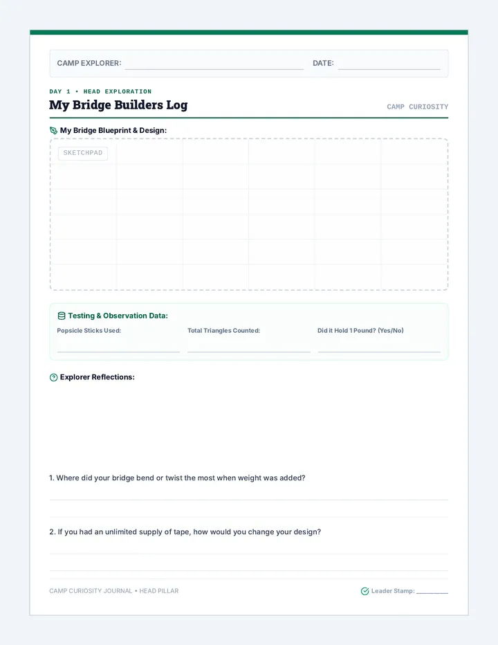
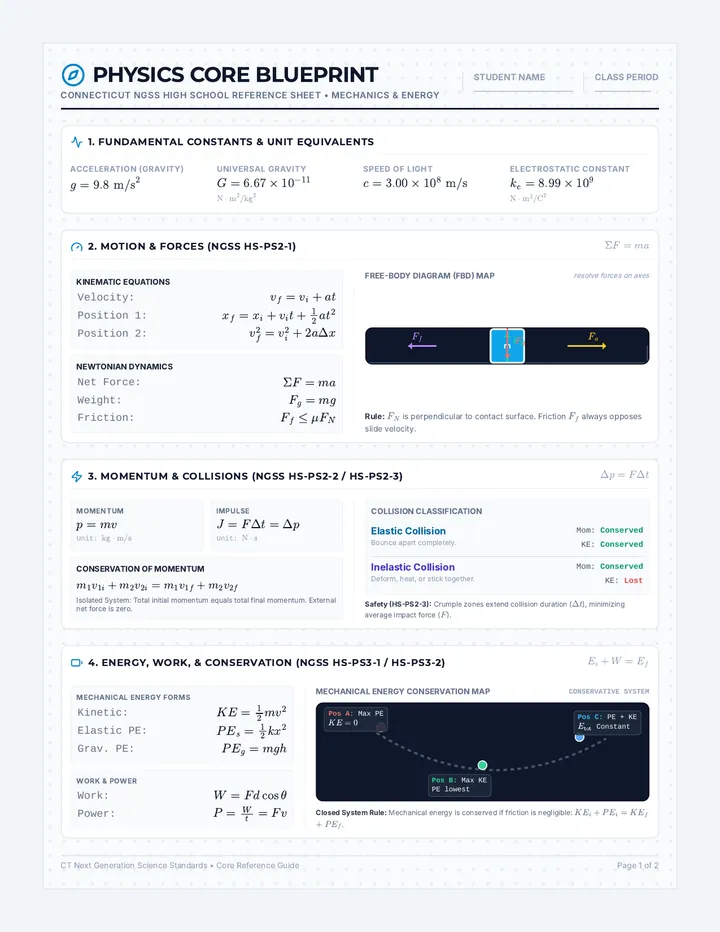
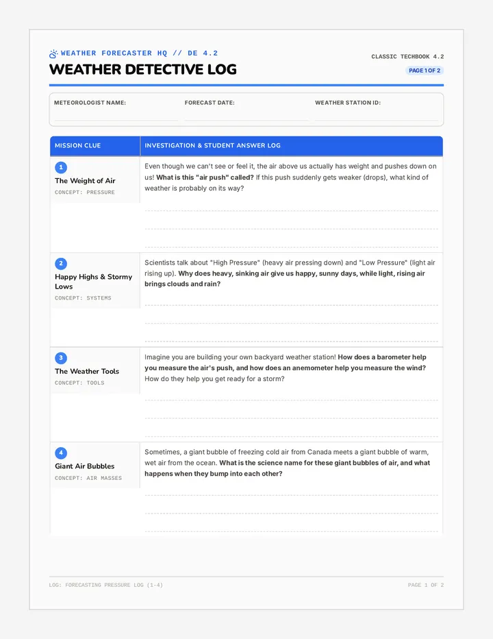
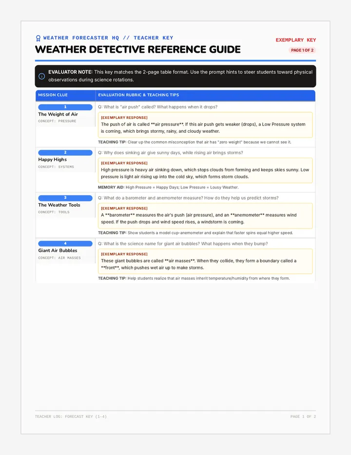
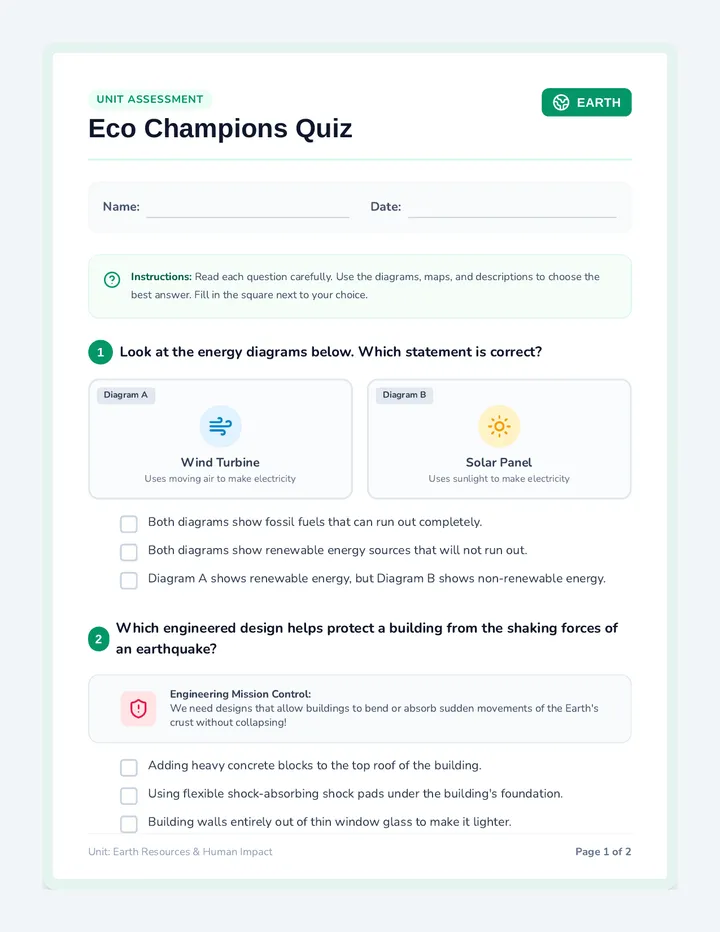
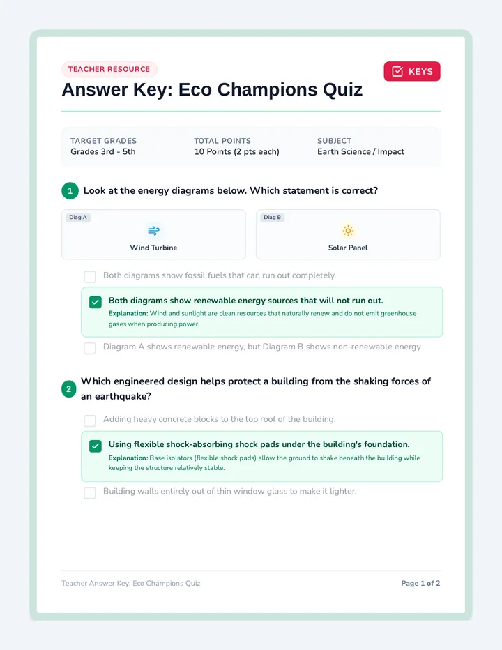
Introduction to Electrical Schematic Symbols
REF: EE-101
Engineers use schematic diagrams —simplified "maps"—to design electrical systems. Standardized circuit symbols allow anyone to understand a circuit's design at a glance.
The Component Key
Component Symbol Function Battery Provides voltage (push) for electrons. Resistor Limits the flow of electrical current. Switch Breaks or completes the loop. Bulb Converts electrical energy into light.
The Integrated Circuit
BATTERY SWITCH (OPEN) RESISTOR BULB
THE GOLDEN RULE
A circuit needs a closed loop (no gaps) for current to flow. If the switch is open or a wire is broken, the bulb stays OFF.
Spark Science Curriculum Handout: Symbol Guide (v1.3)
Circuit Symbols Guided Notes Worksheet Updated Guided Notes: Circuit Sparks
Topic: Basic Circuit Components & Symbols
Name:
Date:
1
Understanding Schematics
A simplified "map" used to design electrical systems is called a ____________________ diagram.
Standardized ____________________ ____________________ are used to represent components so that designs are easy to read globally.
2
The Component Key
Component Symbol Primary Function Battery Provides ____________________ to push electrons. Resistor Limits the ____________________ of electrical current. Switch Breaks or completes the electrical ____________________. Light Bulb An output device that converts energy into ____________________.
3
Integrated Circuit Drawing
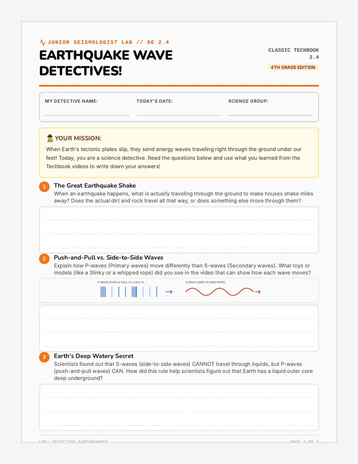
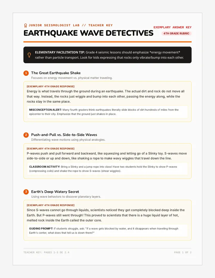
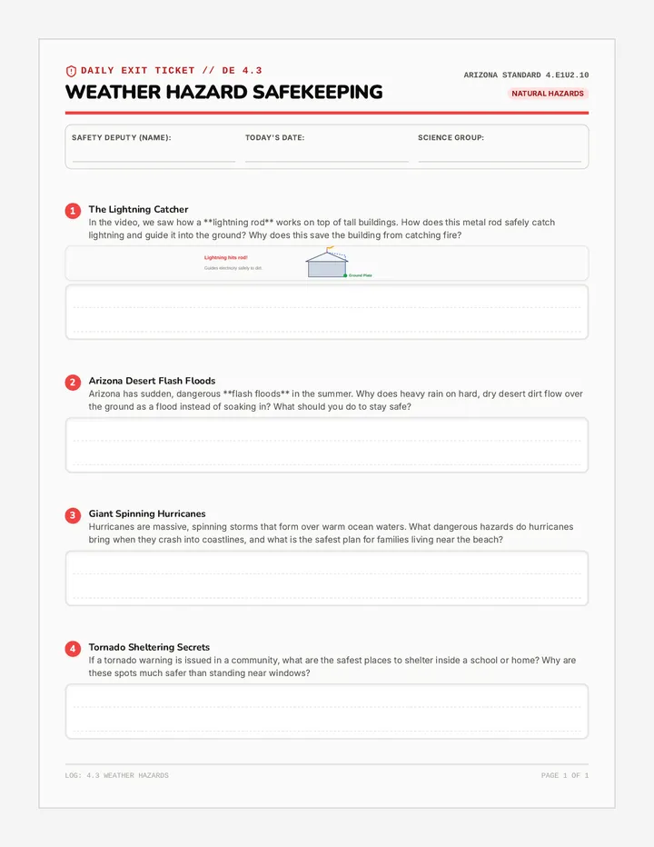
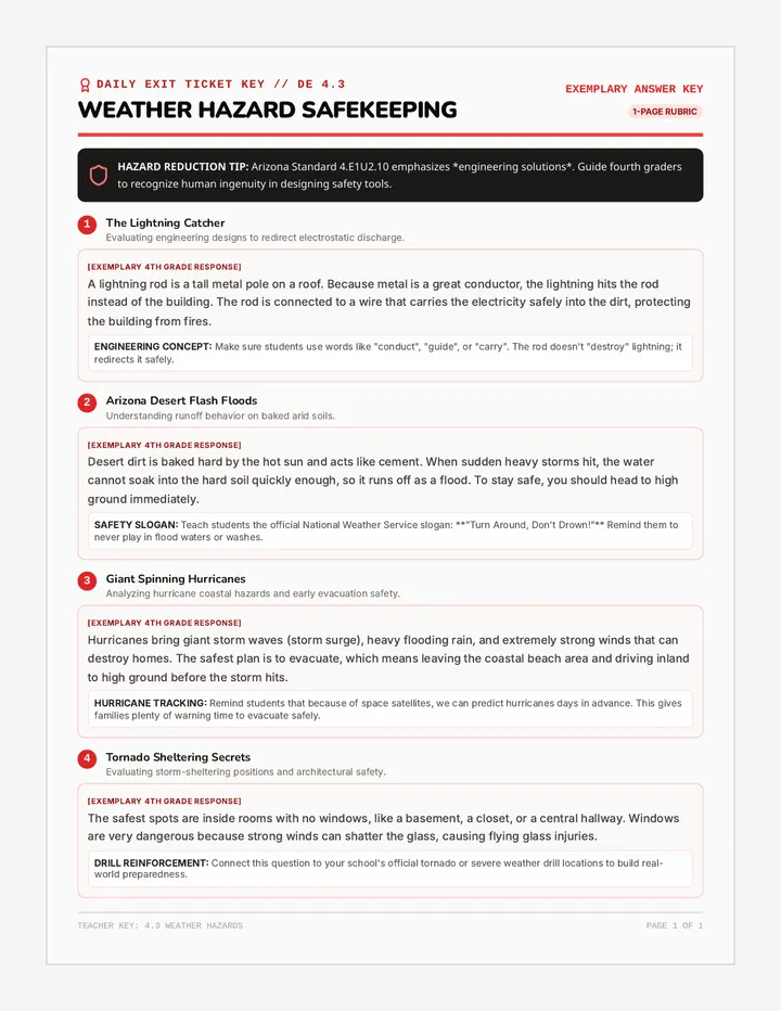
Use the Integrated Circuit from your reading as a guide. Draw a circuit with one battery , one resistor , one open switch , and one bulb in a single loop.
4
Analysis
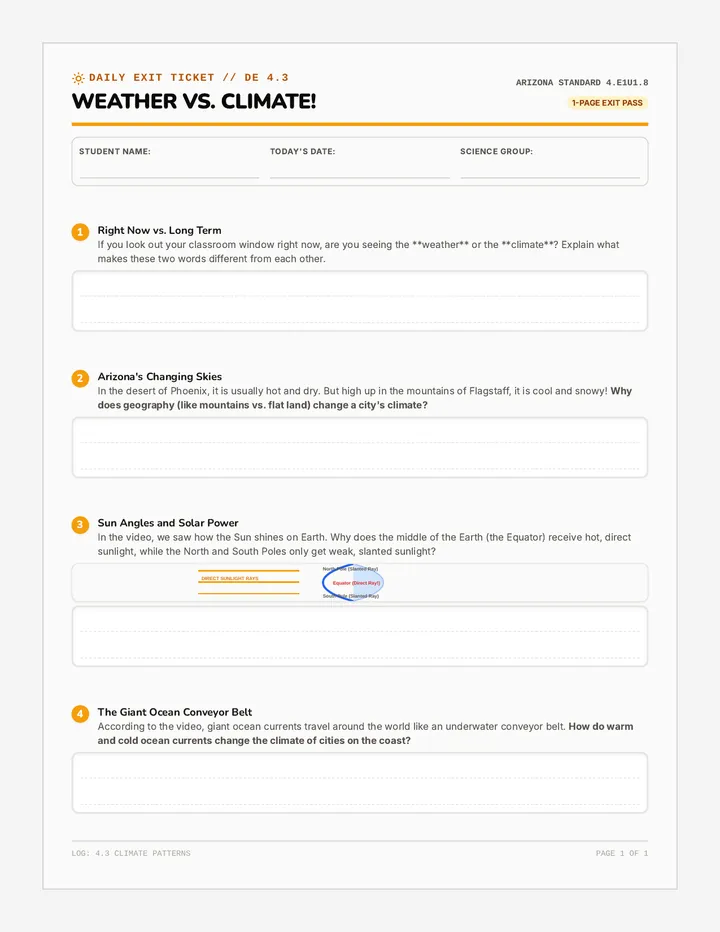
In your drawing above, why will the bulb stay OFF?
Student Worksheet: EE-WKS
Circuit Symbols Master Reading Guide Circuit Blueprint Guide
Part 1: The Language of Schematics
Document No.
REF-101-A
Why Use Symbols?
In the world of electronics, a schematic diagram is a simplified map that shows how a circuit is connected. Instead of drawing realistic pictures of wires and parts, engineers use standardized symbols . This allows a scientist in Tokyo, a student in New York, and an engineer in London to all read the same plan without confusion.
Component Symbol Deep Dive Explanation Battery (Energy Cell) + The battery is the source of energy. It creates electrical "pressure" (voltage) that pushes electrons through the wires. The long line represents the positive (+) terminal. Resistor (Flow Control) Resistors oppose the flow of current. Think of it like a narrow section in a water pipe. It slows down the electricity to protect sensitive parts from getting too much power. Switch (The Gatekeeper) A switch breaks the physical path of the circuit. When the switch is open (as shown), no electricity can cross the gap, and the circuit is "OFF." Light Bulb (The Output) The bulb is a load that converts electrical energy into useful light. It glows when electrons pass through its thin internal filament.
Proceed to Page 2 for Circuit Analysis → Page 1 of 2
Part 2: The Integrated Circuit in Action
Master Schematic Diagram
1. Power Source (Battery) 2. Controller (Switch) 3. Flow Limiter (Resistor) 4. Load (Light Bulb) +
The Path of Electricity
In the diagram above, electricity follows a single path. It leaves the positive (+) terminal of the battery and travels through the top wire. However, it immediately hits the switch . Because the switch is open, the electrons have nowhere to go. This is called an Open Circuit . If we closed the switch, the electricity would flow through the resistor, then light up the bulb, and finally return to the negative (-) terminal.
The Golden Rule: Loops
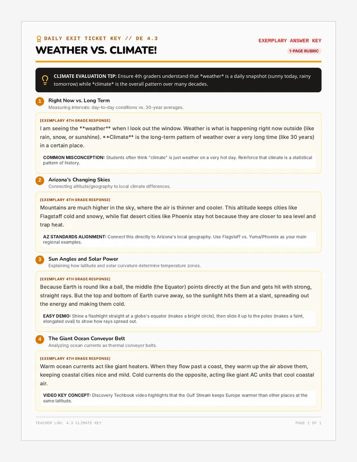
For a circuit to function, it must form a continuous, unbroken loop. This is known as a Closed Circuit . If a wire is cut, a bulb burns out, or a switch is turned off, the loop is broken. Even the most powerful battery in the world cannot move a single electron if there isn't a complete path back to itself. This is why light switches in your house work!
Circuit Symbols Master Reading Guide Final Circuit Blueprint Guide
Part 1: The Language of Schematics
Reference
EE-101-A
Why Use Symbols?
A schematic diagram is a simplified map of an electrical circuit. Instead of realistic drawings, we use standardized symbols . This universal language ensures that anyone can understand how a circuit is built, regardless of the physical appearance of the parts.
Component Symbol Deep Dive Explanation Battery Power Source + The energy source . It provides voltage (electrical pressure) to push electrons. The long line on the symbol always marks the positive (+) side. Resistor Flow Control Resistors limit the flow of current. They prevent sensitive components from receiving too much power by resisting the electricity's flow. Switch Controller A switch breaks or completes the physical path. In this "open" state, the gap stops electricity from flowing entirely. Light Bulb Output Load An output device . It converts electrical energy into light. When current passes through, the internal filament glows brightly.
Part 1 of 2: Symbols Spark Science Curriculum
Part 2: The Integrated Circuit in Action
Functional Schematic Analysis
BATTERY SWITCH (CLOSED) RESISTOR BULB (ON)
The Path of Current
In the diagram above, the switch is closed , completing the loop. Electrical current flows from the positive (+) battery terminal, through the switch, across the resistor, and through the bulb. Because the loop is continuous, electrons can return to the negative (-) terminal. This is a Closed Circuit .
System Balance
Every component plays a role. The battery provides the energy, while the resistor ensures the current doesn't move too fast. Without the resistor, the rush of electricity could overheat the bulb. The bulb acts as the "load," converting the moving energy into bright light for us to see.
Functional Circuit
A closed circuit is like a completed racetrack. As long as the path is unbroken and the battery has power, the bulb will continue to glow. If any part of this path is disconnected, the entire circuit stops immediately.